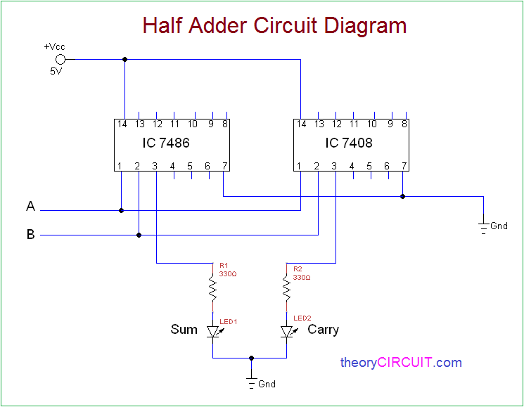

In the next tutorial, we’ll learn how to design half and full subtractor circuits using VHDL. In the above figure, one case is highlighted as a=1, b=1, and cin=0, with the outputs of sum=0 and carry=1. architecture of full adder-Ĭompare the outputs “sum” and “carry” with the given truth table. (The full-adder circuit consist of two half adder and one OR gate). We’ll build a full-adder circuit using the “ half-adder circuit” and the “ OR gate” as components or blocks. Here, we’ll also use that style rather than the data-flow modeling style. In the previous tutorial, we designed one Boolean equation digital circuit using a structural-modeling style of the VHDL programming. Let’s write a VHDL program for this circuit. Next, let’s move on to the full adder circuit and its design. For the a=1 and b=0 inputs, the outputs are sum=1 and cry=0, which are highlighted in the figure. Binary Arithmetic Half Adder and Full Adder Slide 4 of 20 slides SeptemThe Sum 1 + 1 in Binary Arithmetic We have just noted that the decimal number 2 is represented in binary as 10. Verify the ‘sum’ and ‘cry’ output waveforms with the given truth table. Next, compile the above program, creating a waveform file with all of the necessary inputs and outputs that are listed, and simulate the project. To refresh your memory about how this works, go through the first two VHDL tutorials ( 1 and 2) of this series. “ architecture ” describes the operation of the circuit, which refers to how the output is generated from the given input.In addition to the A and B, there is an additional C input bit. The half adder consists of two input bits, A and B, while the full adder features three input bits. The full adder features three logic gates: an OR gate, three AND gates, and two EX-OR gates. As per the circuit given above, we have two inputs ‘a,’ ‘b,’ and two outputs, ‘sum’ and ‘cry.’ There are two logic gates in the half adder that include the EX-OR gate and the AND gate. “ entity ” describes the input-output connections of the digital circuit.In that tutorial, we learn how to design a project, edit and compile a program, create a waveform file, simulate the program, and generate the final output waveforms. The input values for 1 and 0 are 2.3 and 0 V, respectively. The voltage output values are shown in brackets. The table consists of 32 sets of input combinations (A 1 A 0, B 1 B 0, C 0 ) with the corresponding outputs S 1, S 0, C 2, and /C 2. However, first it’s important to review the step-by-step procedure provided in VHDL Tutorial – 3. What is a 2 bit full adder truth table (C) Experimental truth table for the 2-bit full adder. We’ll also verify the output waveforms with the given truth table. Now, we’ll write a VHDL program, compile and simulate it, and get the output in a waveform.

Verify the output waveform of the program (digital circuit) with the half and full-adder circuits’ truth tables.Write a VHDL program to build half and full-adder circuits.In the previous tutorial VHDL Tutorial – 9, we learned how to build digital circuits from given Boolean equations.
Full adder and half adder truth table series#
Note: it’s recommended to follow this VHDL tutorial series in order, starting with the first tutorial.


 0 kommentar(er)
